AEAC fixed-wing concept proposal
My concept proposal to UVic AERO for the 2027 AEAC competition aircraft: a fast twin-motor fixed-wing. One option for the team to consider, not a final design.
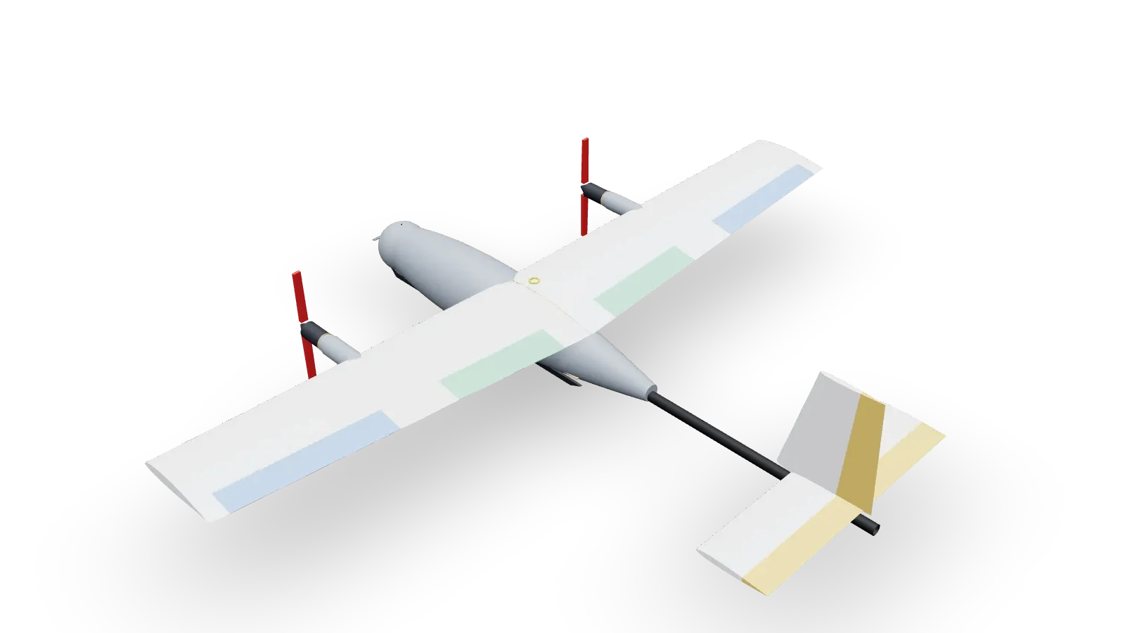
This is a proposal, not the team’s aircraft. I put it forward for UVic AERO’s design review on 1 October 2026. Nothing here has been built.
The problem
UVic AERO is entering the 2027 AEAC student UAS competition. The first task is a herd survey: sprint 5 km to the survey area, fly a grid, then orbit and read 3 cm ear tags, all in 30 minutes on one battery. Time to the survey area is ranked.
The rules cap the aircraft at 15 kg, electric only, with no parachute. It has to fly in wind up to 10 knots, gusting 20.
This is the fast option: dash at 45 m/s, survey at 20 m/s, with enough battery that endurance is never the limit.
- Span
- 2.30 m
- Wing area
- 0.736 m²
- Flying mass
- 7.15 kg
- Design mass
- 9.5 kg
- Dash
- 45 m/s
- Stall, clean
- 11.4 m/s
Everything is sized for 9.5 kg, about 2.3 kg more than it flies at today, so payload can be added later without a redesign.
How this was made
I set the concept and requirements, decided what to compare, and chose between the results. I built the analysis code (AeroSandbox, plus a mission simulation) and the Fusion models AI-assisted. I then checked the aerodynamics by building the aircraft in flow5 and comparing values, and ran a modal study of the tail in Fusion.
Getting to this layout
I went through six layouts in three rounds. Each round I described what I wanted to compare, generated the models AI-assisted, and chose a direction.
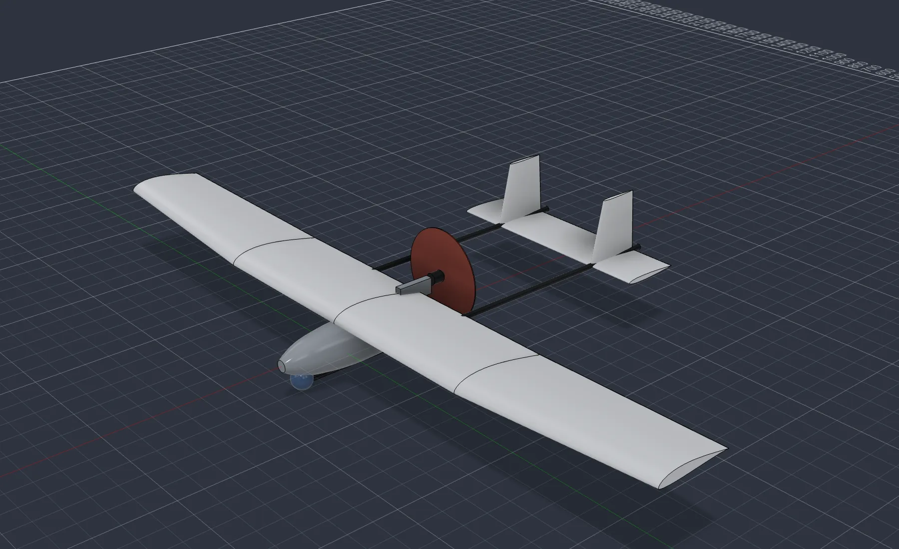
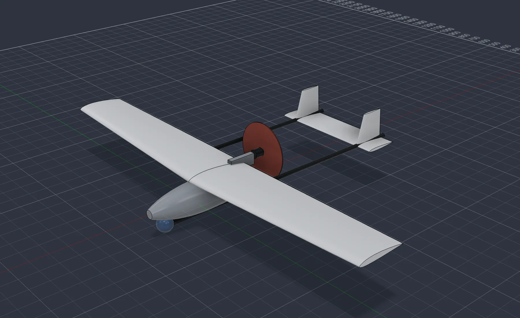
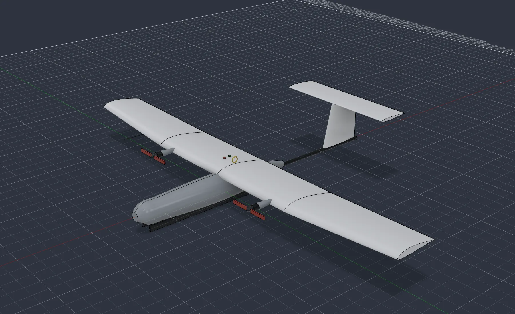
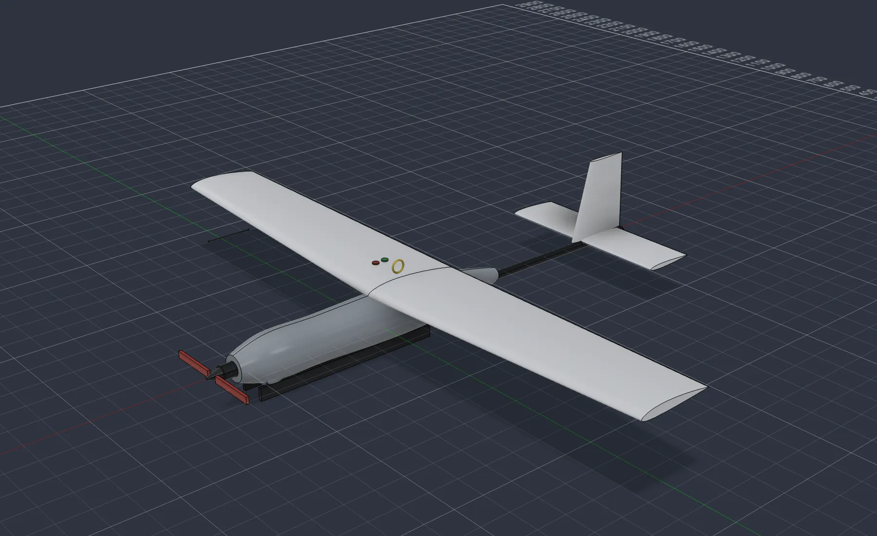
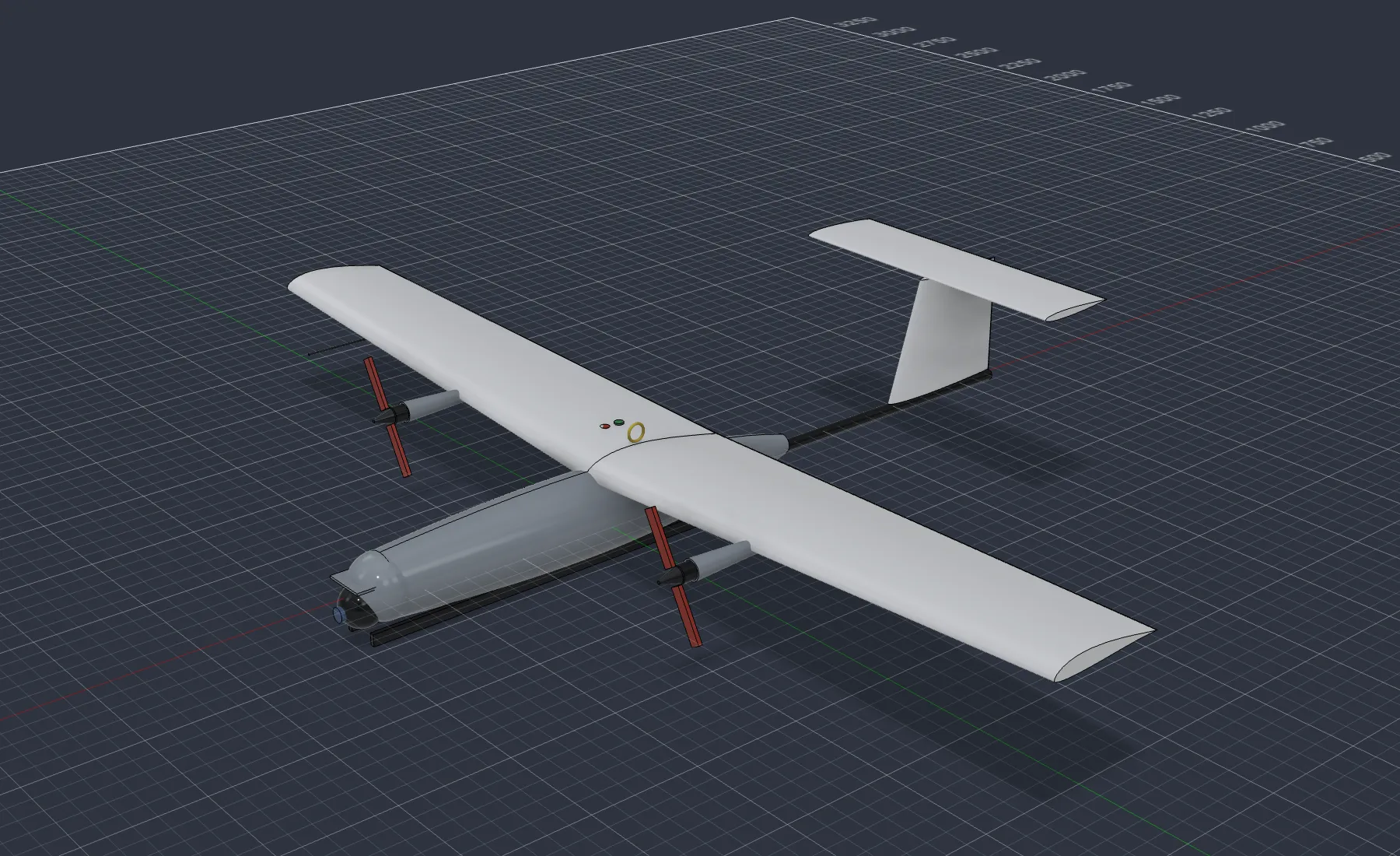
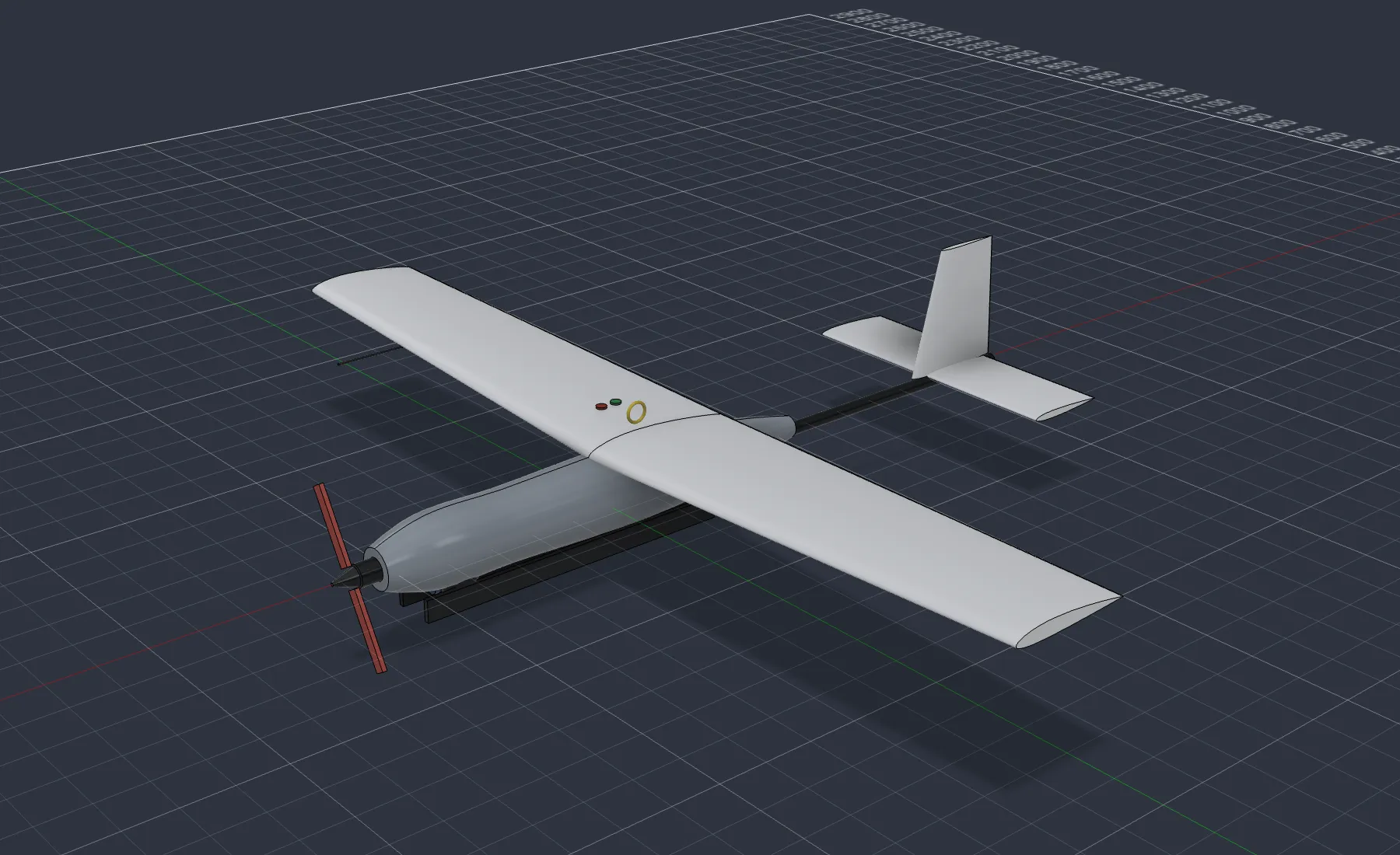
The first round was a twin-boom pusher. I dropped it because the team wants to hand-launch, and a propeller behind the wing is in the way of the throw. The second round put the motors in front and split on the camera: in the nose with a motor on each wing, or under the chin behind a nose motor. The proposal keeps the nose camera and twin motors from 2a and the low tail from 2b.
Key decisions
Airfoil
| RG15 | HQ 2.5/12 ✓ | |
|---|---|---|
| Thickness | 8.9% | 12.0% |
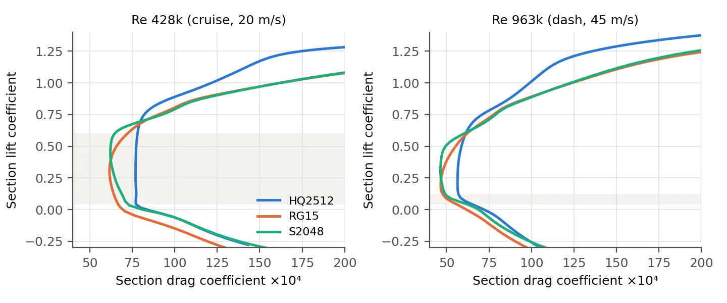
| Drag at dash (cd) | 0.0051 | 0.0060 |
| Max lift at landing | 1.20 | 1.30 |
| Fits the 25 mm spar | No | Yes |
Chose HQ 2.5/12 because it has the lowest dash drag of any section thick enough to hold the 25 mm spar. The thin speed sections (RG15, S2048, MH32) were faster on paper but too thin at the root.
Wing size
| 2.1 m span | 2.3 m span ✓ | 2.5 m span | |
|---|---|---|---|
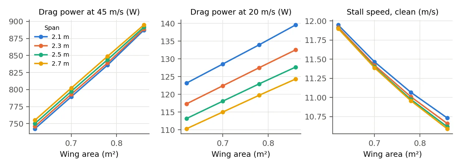
| Cruise drag | Higher | Baseline | About 4 W lower |
| Stall speed | Above 12 m/s | 11.4 m/s | Lower |
| Weight and roll rate | Lighter, quicker | Baseline | Heavier, slower |
Chose 2.3 m span because it sits at the knee of the curves. Going to 2.5 m saves about 4 W in cruise for a heavier wing that rolls more slowly; going smaller pushes stall above 12 m/s.
Motor layout
| Single nose motor | A motor on each wing ✓ | |
|---|---|---|
| View from the nose camera | Behind the propeller | Clear |
| Slipstream over the stabiliser | Yes | No, passes outboard |
| If one motor fails | Glide | Strong yaw, needs managing |
Chose A motor on each wing because the camera needs a clear view from the nose to read the ear tags. The cost is the one-motor-out case, covered below.
Tail
| T-tail | Low tail ✓ | |
|---|---|---|
| Flying mass | 7.28 kg | 7.15 kg |
| Fin area | About 25% larger | Baseline |
| Elevator | Clean air, above the wake | Behind the wing |
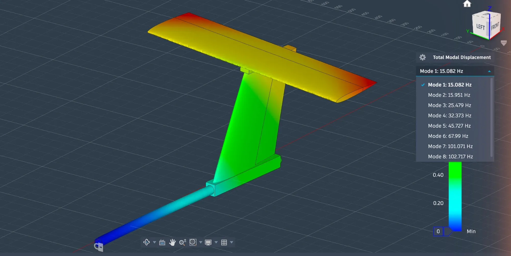
| Mode near prop frequency | Yes, 68 Hz | Not in the estimate |
Chose Low tail because the T-tail's modes land where the propellers turn at loiter and cruise. Its clean-air elevator isn't worth that, or the extra weight.
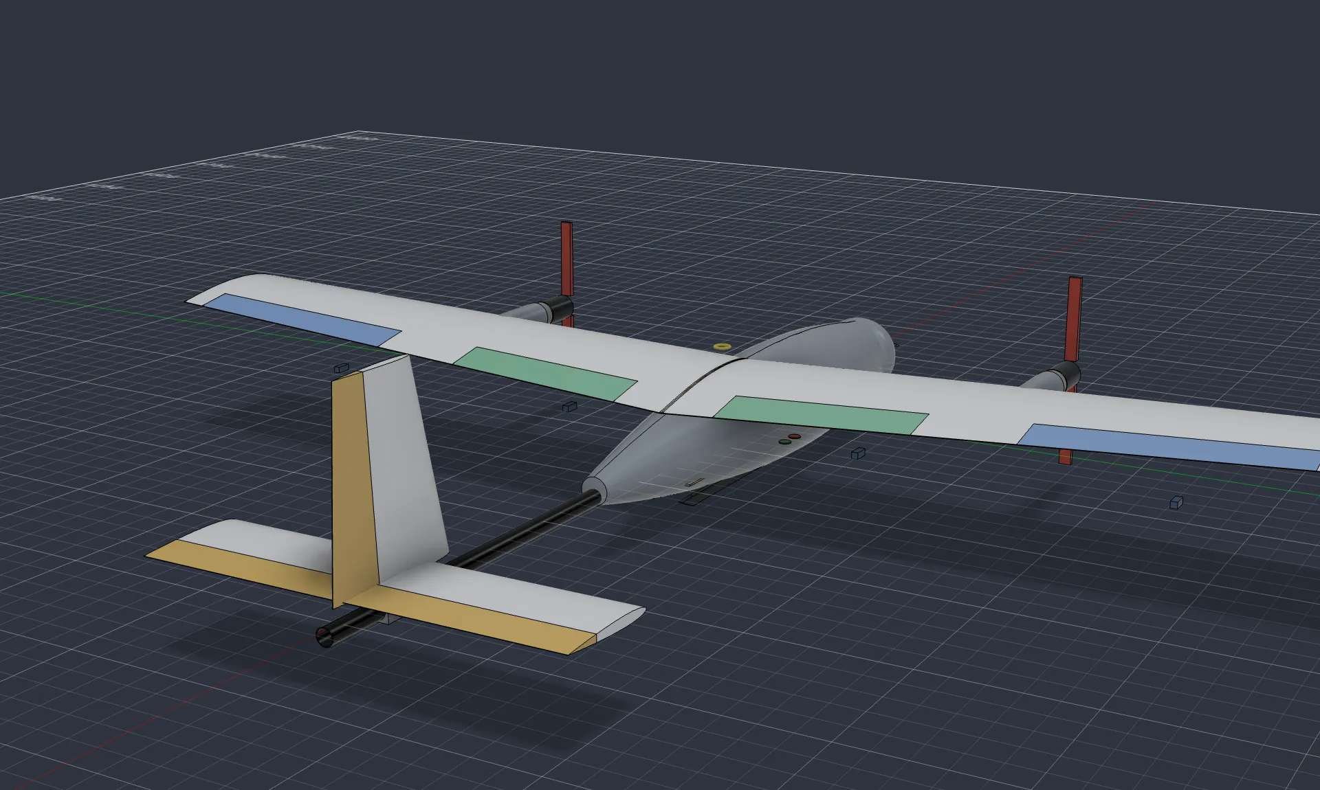
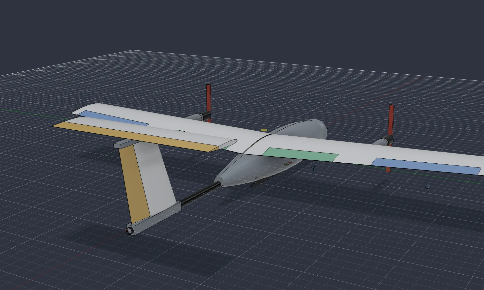
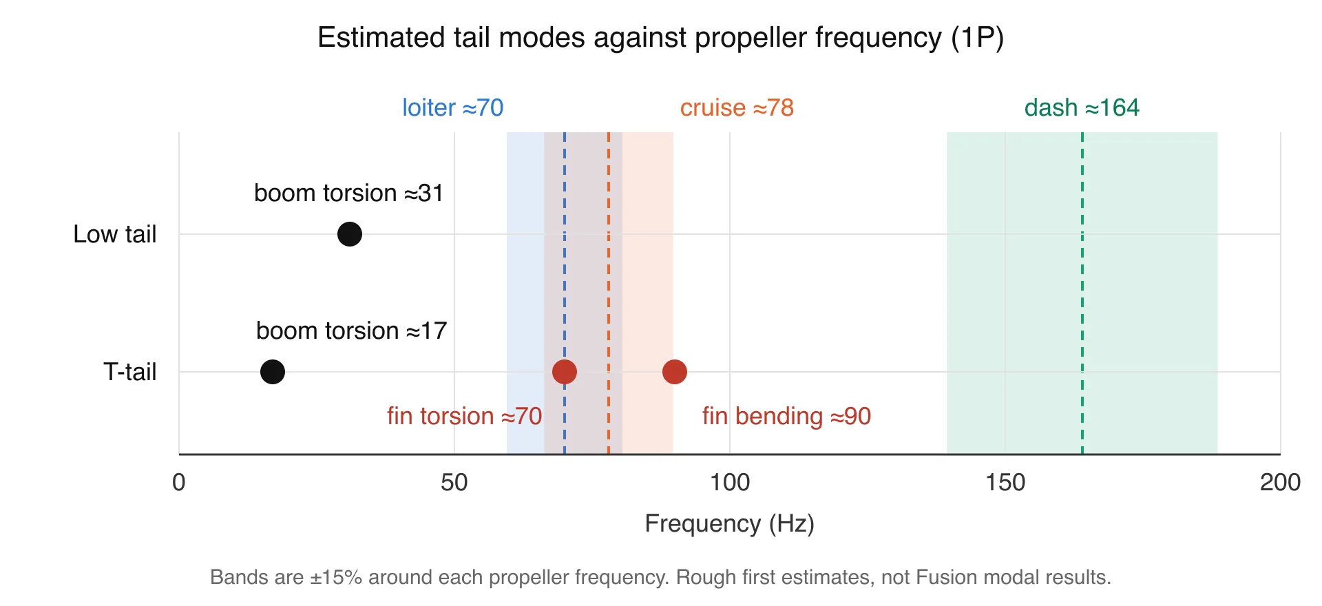
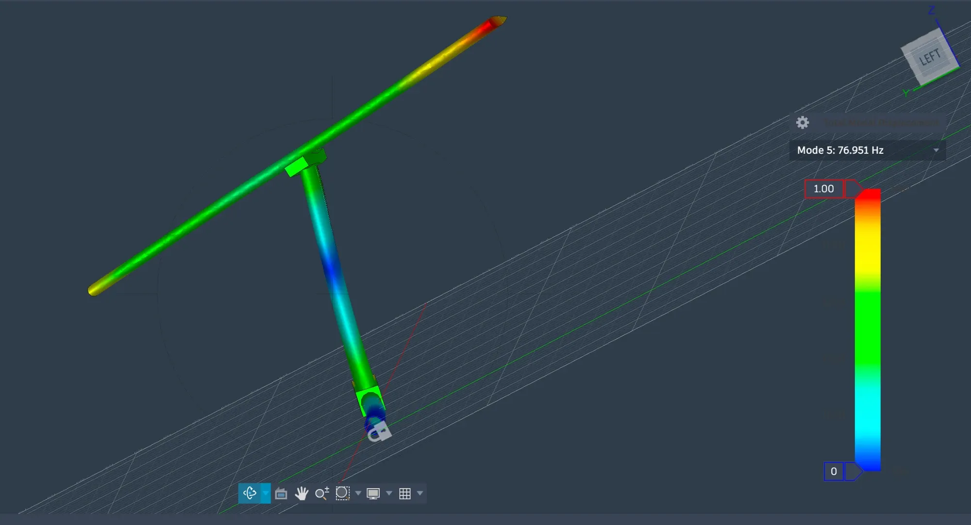
The chart shows the first estimates. The modal study in Fusion agreed: the T-tail has a mode at 68 Hz, and its carbon spars on their own have one at 77 Hz. The propellers turn at about 70 Hz at loiter and 78 Hz at cruise, and the target is to keep every mode at least 15% away from both.
Battery
| 12S2P pack ✓ | 12S3P pack | |
|---|---|---|
| Flying mass | 7.15 kg | 8.06 kg |
| Endurance to 20% reserve | 70 min | 104 min |
| Charge left at 30 min | 60% | 72% |
Chose 12S2P pack because it already gives 70 minutes against a 40-minute target. The larger pack stays as the option for heavier payloads.
Drag and power
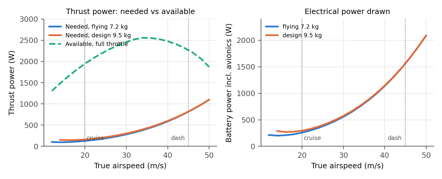
Total drag is 6.4 N at 20 m/s and 18.1 N at 45 m/s, including a 1.35 factor for student build quality.
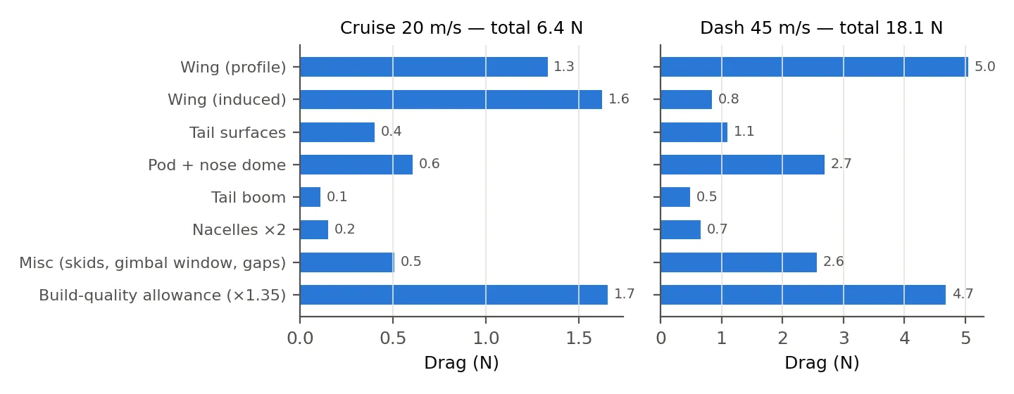
The dash draws about 1,560 W at 76% throttle and cruise about 258 W. The motors have about three times the power the dash needs.
Structure
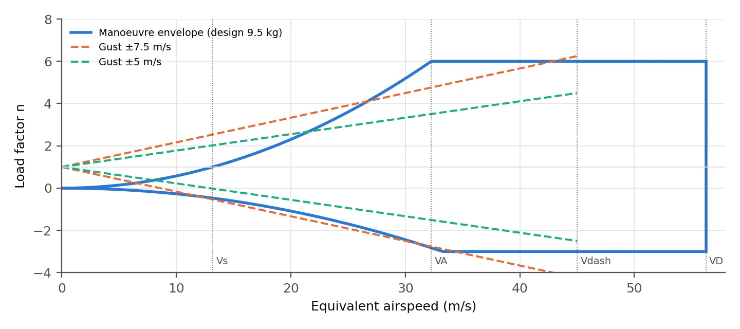
The design case is 9.5 kg at +6 and −3 g, with a 1.5 factor on top for ultimate load. A 5 m/s vertical gust at dash speed gives 4.5 g and a 7.5 m/s gust gives 6.2 g, so the dash is only flown when gusts are moderate.
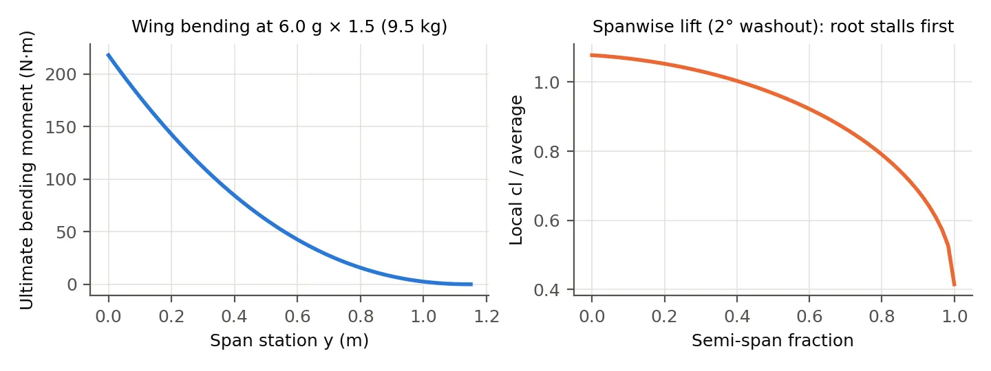
The main spar is a 25 × 1.5 mm carbon tube at 28% chord. At ultimate load the root bending moment is 218 N·m, which puts the tube at 355 MPa against an allowable of about 600 MPa. With 2° of washout the root reaches its maximum lift first, so the aircraft should drop its nose in a stall, not a wing.
The biggest risk: one motor out
If one motor stops while the other is at high power, the aircraft yaws hard. The table compares that yawing moment with what full rudder can hold.
| Phase | Speed | One motor, full throttle | One motor, trim thrust | Full rudder holds |
|---|---|---|---|---|
| Just after launch | 14.3 m/s | 30.2 N·m | 3.7 N·m | 5.1 N·m |
| Cruise | 20.0 m/s | 27.9 N·m | 3.5 N·m | 10.1 N·m |
| Dash | 45.0 m/s | 16.3 N·m | 10.0 N·m | 50.9 N·m |
At trim power the rudder copes everywhere. At full power it only copes at dash speed, and a fin big enough to fix that would need about six times the area. So the plan is:
- Cap the throttle at 60% for launch and climb, and 85% for the sprint.
- Feed each motor’s RPM to the flight controller, and cut the good motor within about 0.3 s if the two diverge. The aircraft then glides to a landing.
Mission simulation
The simulation flies the whole task: launch, climb to 50 m, 5 km of sprint laps, a survey grid, six tag orbits, then loiter to the reserve.
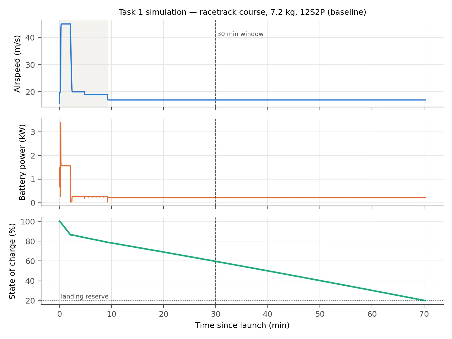
Even with 60% more drag than the model predicts, the pack lasts over an hour. Endurance is not what limits this design. Gust loads, flutter and the motor-out case are.
Result
- 5 km sprint
- 129 s
- Top speed
- about 54 m/s
- Charge left at 30 min
- 60%
- Endurance to 20% reserve
- 70 min
- Static margin
- 12%
- Spar stress at ultimate
- 355 of 600 MPa
On paper the proposal reaches 45 m/s, finishes the task in about 9 minutes and has more than twice the endurance it needs. These are simulation numbers, not test results. The list below is what has to happen before I would trust them.
Gallery
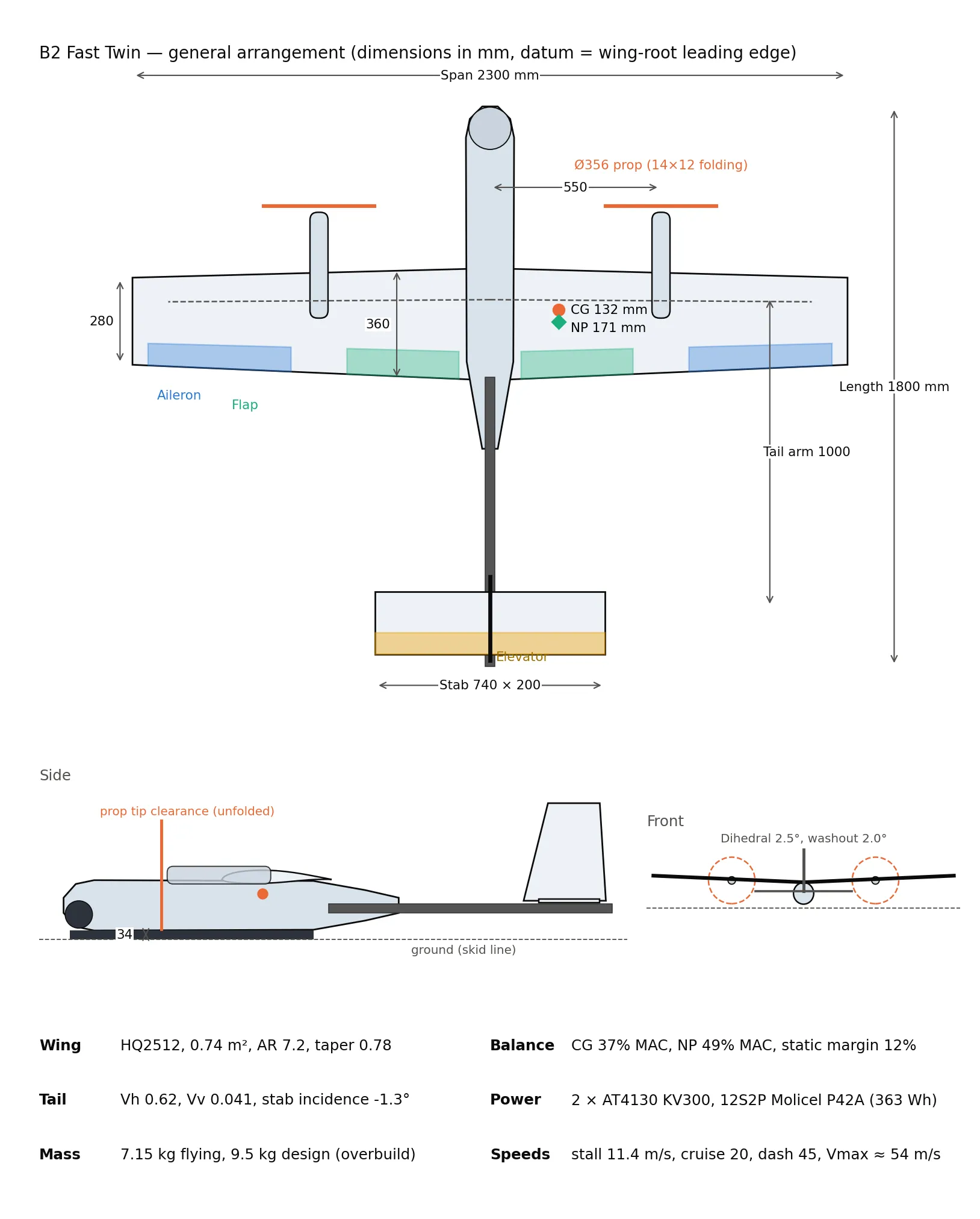
06Top view. Flaps in green, ailerons in blue. Front view Side view Low tail, rear view From underneath T-tail variant